Make a copy of your original .dwg file, and give
the copy a different name. This is done so as to avoid modifying the original
.dwg file. The copy will be modified in a way that might
make it difficult to perform edits in the future, so the original
.dwg file is retained. You can skip this step if
you are certain your drawing contains no unexploded entities.
We recommend appending the letter x to the original file name when creating
the new one to signify eXploded since the main difference between the original
and the working copy is that any complex entities present in the original file
will be exploded in the copy. If for example, your original file is named
abc.dwg , name the working copy
abcx.dwg or
abc_x.dwg .
Method A:
Open the original .dwg file. If you are
currently editing the original .dwg file,
save it by typing qsave on the command line or
clicking the 'floppy disk' icon.
Pick File -> Save As from the main menu bar.
Give the new drawing a unique name. The original file will be left intact.
Method B:
Using Microsoft Windows Explorer, copy the .dwg
file to a new name.
Remove all spurious entities from your drawing.
Erase anything that will not appear on the artwork/photomask. This includes
title blocks, notes, layers containing unneeded information, etc. The final
drawing should contain only those entities that will appear on the photoplot or
photomask.
Make sure all entities are in Model Space.
Make sure everything you draw is in Model Space and not in Paper Space. Paper space
should not be used at all. If you inadvertently draw in Paper Space, you can move the
entities to Model space. by using the "Copy with Base Point" selection on the "Edit"
menu, followed by "Paste" (applied from within Model Space), then delete the items from Paper Space.
Procedure:
Switch to Paper Space by clicking the appropriate "Layout" tab at the bottom of the screen. If you have
only one Paper Space layout, the tab is labelled "Layout1" by default.
Select "Copy with Base Point" from the "Edit" menu. When prompted to specify the base point, type
in "0,0" and press enter.
When prompted to select objects, type in "all" and press enter. The entities should be copied to the
clipboard.
Switch to Model Space by clicking on the "Model" tab at the bottom of the screen.
Paste the entities you copied by pressing Ctrl-V or "Paste" from the "Edit" menu. When prompted to
specify the insertion point, type "0,0" and press enter.
Set scale and measurement units.
Make sure the drawing is drawn at 1:1 scale. CAD drawings should always be drawn
at actual size to facilitate direct measurement within the CAD application.
Units are totally arbitrary in AutoCAD. The numbers used in a drawing can mean
anything you wish. Unless you tell us otherwise, we assume your drawing units are
inches. If you use other units, you must specify them in your readme.txt file or
place a reference line or rectangle in your drawing. This reference mark will be
plotted along with your other data, so it should be located outside of the critical
image area. Commonly used units include inches, millimeters, and microns.
Set origin.
Make sure the origin (0,0 location) of the drawing in the WCS (World Coordinate
System) is set such that the origin is at the extreme lower left corner of the
drawing or at the center. Setting the origin at the center of a drawing with
horizontal and vertical symmetry makes sense. For rectangular drawings using the
lower lefthand corner is often the best choice.
Procedure:
Type move at the command prompt.
When prompted to Select objects type all
and press enter. Press enter a second time to finish selecting objects.
When prompted Specify base point or displacement:
click on the endpoint, midpoint, center, etc. of the object or place you want to use as the origin
using object snaps.
Type 0,0 when prompted Specify second point
of displacement or <use first point as displacement>:and press enter.
Change fonts to romans.shx.
AutoCAD supports three types of text fonts: .shx, .ps, and TrueType. .shx fonts are the original
vector font format supported by AutoCAD and the only one recognized by Dxf2gbr. Dxf2gbr uses the romans.shx
font by default. It is possible to utilize other .shx fonts, but this must be done manually by specifying
the font to use in the readme file. Dxf2gbr will convert text drawn in any font, whether .shx, .ps, or
TrueType to romans.shx automatically, but letter spacing and position may vary from the original font.
For this reason it is best to convert all text in your drawing to the romans.shx font to be assured that letter
positioning is correct in the resulting Gerber file.To change the font(s) in your drawing to romans.shx, use the "Style" command to redefine each of the
text styles in your drawing.
Explode blocks, dimensions, hatching, and mtext.
The Laserlab dxf2gbr translator does not recognize compound objects such as
blocks. Blocks and other compound objects must be exploded to decompose them into
simpler entities like lines, arcs, and polylines.
Dxf2gbr does not support hatched objects of any kind. If your drawing contains hatching,
it must be there only to guide the Laserlab CAD operator or exploded into overlapping parallel
lines before passing it on to us. Hatching a drawing to fill odd-shaped areas makes sense if it
is not easy or convenient to use "fat" polylines or solids to create the desired shape.
If AutoCAD hatches are present in your drawing, we will use the outline data to re-hatch
it using another program before passing it through Dxf2gbr. This means associative hatching
must be used. If the hatch outline is not present we cannot use it.
The rehatching process is done with CAD operator assistance and increases both the
cost of conversion and processing time. To keep conversion costs low and turnaround rapid,
we recommend using polylines with width > 0 (fat polylines) and 3 (triangular) or 4 vertex
polygons created with the "solid" command.
If you choose to included hatched areas in the drawing you send to us, make sure the outline data
is included and leave them unexploded so we can manipulate them easily.
Dimensions must be exploded twice. First the dimension itself is exploded into lines
and mtext, then the mtext (multi-line text) must be exploded into dtext (single line text).
Method A: (best if you have only a few items to explode and know their locations)
Type explode at the command prompt.
Click on the compound entities one-by-one.
Method B: (preferred method, but more complex)
Type explode at the command prompt.
Type 'filter (note the tick (apostrophe)).
Add one or more of "block", "dimension" "hatch", and "text" to the object selection filters
dialog box using the scroll box. Click "add to list". Click "apply" when done.
Type "all" when asked to select objects.
Press return as many times as required to complete.
Explode groups.
Groups must be exploded for the same reason that blocks must be. The Laserlab dxf2gbr
translator does not recognize any type of compound object.
To explode groups:
Use the list command to select grouped objects and determine the group name.
Type group at the command prompt.
This should bring up a dialog box.
Purge drawing.
Remove all unused compound entities, line styles, text styles, layers, etc.
from the drawing. These items are not visible but are stored in the
.dwg file. Purging the drawing can
dramatically reduce the .dwg file size.
Procedure:
Type purge at the command prompt and press enter.
Type all and press enter.
Press enter when prompted Enter name(s) to purge <*>:
Press enter when prompted Verify each name to be purged? [Yes/No] <Y>:
Repeat steps 1-4 until the following is displayed:
No unreferenced blocks found.
No unreferenced layers found.
No unreferenced linetypes found.
No unreferenced text styles found.
No unreferenced shape files found.
No unreferenced dimension styles found.
No unreferenced mlinestyles found.
No unreferenced plotstyles found.
Use AutoCAD "dxfout" command to produce .dxf file(s).
There is a one-to-one correspondence between .dxf and .gbr files. Each .dxf file
must contain exactly those items you wish to have appear on your photoplot or
photomask. In the following procedure, you generate one or more .dxf files by turning
on and off layers in the drawing, then outputting a .dxf file with only the visible
entities. These steps are repeated until you create all the desired .dxf files.
Procedure:
Zoom out so that everything you want to output is visible. Leave a border by zooming ".9x".
This leaves room to easily select the objects to output using a selection window.
Open the layer properties manager by clicking the "layers" icon (looks like a stack of
three white sheets of paper).
Turn off all layers not pertinent to the artwork you wish to produce.
Turn on all layers you wish to have appear on the artwork. Close the layers dialog box.
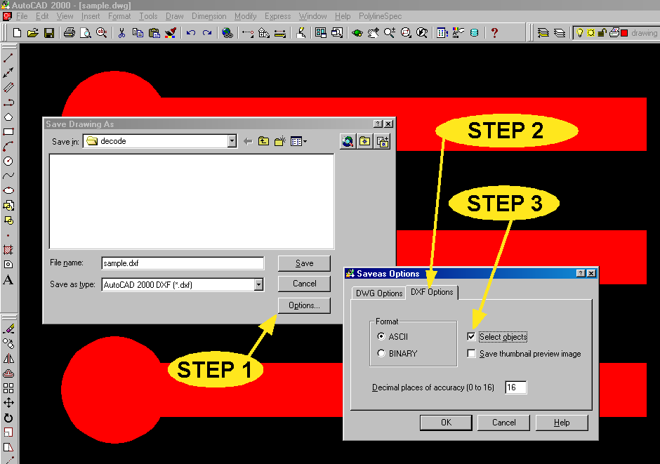
Type "dxfout" at the command prompt and press enter. The "Save Drawing As" dialog box will appear.
Step 1: Click the "Options" button at the lower righthand side of the dialog box. The "Saveas Options"
dialog box appears.
Step 2: Click the "DXF Options" tab.
Step 3: Check mark the "Select objects" checkbox. Click "OK" to close the dialog box.
Type a file name in the "file name" field. Click "Save" to close the dialog box.
Select all the items on the screen using a selection window. Press enter. This should
save only the visible entities to a .dxf file.
Repeat steps 2-10 to create other .dxf files as required.